Step 1 | Select and click Edit ( ) for your Firewall Threat Defense device. The Interfaces page is selected by default. ) for your Firewall Threat Defense device. The Interfaces page is selected by default. |
Step 2 | Click Edit () for the interface you want to edit. |
Step 3 | In the
Name field, enter a name up to 48 characters in
length.
You cannot start the name with the phrase "cluster". It is reserved for
internal use.
|
Step 4 | Enable the interface by checking the Enabled check box. |
Step 5 | (Optional) Set this interface to Management Only to limit traffic to management traffic; through-the-box traffic is not allowed. |
Step 6 | (Optional) Add a description in the Description field.
The description can be up to 200 characters on a single line, without carriage returns.
|
Step 7 | In the Mode drop-down list, choose None.
Regular firewall interfaces have the mode set to None. The other modes are for IPS-only interface types.
|
Step 8 | From the
Security
Zone drop-down list, choose a security zone or add a new one by
clicking
New.
The routed interface is a Routed-type interface, and can only
belong to Routed-type zones.
|
Step 9 | See Configure the MTU for information about the MTU. |
Step 10 | In the Priority field, enter a number ranging from 0–65535.
This value is used in the policy based routing configuration. The priority is used to determine how you want to route the traffic across multiple egress interfaces. For more information, see Configure Policy-Based Routing Policy.
|
Step 11 | Click the
IPv4 tab. To set the IP address, use one of the
following options from the
IP
Type drop-down list.
High Availability, clustering interfaces
only support static IP address configuration; DHCP and PPPoE are not
supported.
-
Use Static IP—Enter the IP address and subnet mask. For point-to-point connections, you can specify a 31-bit subnet mask (255.255.255.254 or /31). In this case, no IP addresses are reserved for the network or broadcast addresses. You cannot set the standby IP address in this case. For High Availability, you can only use a static IP address. Set the standby IP address on the page, click High Availability in the Monitored Interfaces area. If you do not set the standby IP address, the active unit cannot monitor the standby interface using network tests; it can only track the link state.
-
Use
DHCP—Configure the following optional parameters:
-
Obtain default route using
DHCP—Obtains the default route from the DHCP server.
-
DHCP route
metric—Assigns an administrative distance to the learned route,
between 1 and 255. The default administrative distance for the learned routes
is 1.
-
Use PPPoE—If the
interface is connected to a DSL, cable modem, or other connection to your ISP,
and your ISP uses PPPoE to provide your IP address, configure the following
parameters:
-
VPDN Group
Name—Specify a group name of your choice to represent this
connection.
-
PPPoE User
Name—Specify the username provided by your ISP.
-
PPPoE Password/Confirm
Password—Specify and confirm the password provided by your ISP.
-
PPP
Authentication—Choose
PAP,
CHAP, or
MSCHAP.
PAP passes
a cleartext username and password during authentication and is not secure. With
CHAP, the client returns the encrypted [challenge plus password], with a
cleartext username in response to the server challenge. CHAP is more secure
than PAP, but it does not encrypt data. MSCHAP is similar to CHAP but is more
secure because the server stores and compares only encrypted passwords rather
than cleartext passwords as in CHAP. MSCHAP also generates a key for data
encryption by MPPE.
-
PPPoE route
metric—Assign an administrative distance to the learned route.
Valid values are from 1 to 255. By default, the administrative distance for the
learned routes is 1.
-
Enable Route Settings—To manually configure the PPPoE IP address, check this box and then enter the IP Address.
If you select the Enable Route Settings check box and leave the IP Address blank, the ip address pppoe setroute command is applied as shown in this example:
interface GigabitEthernet0/2
nameif inside2_pppoe
cts manual
  propagate sgt preserve-untag
  policy static sgt disabled trusted
security-level 0
pppoe client vpdn group test
pppoe client route distance 10
ip address pppoe setroute
-
Store Username and Password
in Flash—Stores the username and password in flash memory.
The
Firewall Threat Defense
device stores the username and password in a special location of NVRAM.
|
Step 12 | (Optional) See Configure IPv6 Addressing to configure IPv6 addressing on the IPv6 tab. |
Step 13 | (Optional) See Configure the MAC Address to manually configure the MAC address on the Advanced tab. |
Step 14 | (Optional) Set the duplex and speed by clicking .
-
Duplex—Choose Full or Half. SFP interfaces only support Full duplex.
-
Speed—Choose a speed (varies depending on the model).For SFPs, choose Detect
SFP to detect the speed of the installed SFP
module and use the appropriate speed. Duplex is always full,
autonegotiation is enabled, and FEC is set to auto. For
dual-speed transceivers, the lower speed is used. This option is
useful if you later change the network module to a different
model, and want the speed to update automatically.
Some switches and transceivers don't support
autonegotiation, especially for higher speed interfaces. In this
case, set the interface on the Firewall Threat Defense to a manual speed and also disable
Auto-negotiation so the link can come
up.
Note | You cannot modify the speed of a high availability or a cluster control link
interface. |
-
Auto-negotiation—Set the interface to negotiate the link status and
flow control.
Except for the 1100 and
2100, autonegotiation is set separately from the speed.
Some switches don't support autonegotiation,
especially for higher speed interfaces. In this case, set the
interface on the Firewall Threat Defense to a manual speed and also disable
Auto-negotiation so the link can come
up.
-
Forward Error Correction Mode—For 25Gbps and higher interfaces,
enable Forward Error Correction (FEC).
For an EtherChannel member interface, you must configure FEC before
you add it to the EtherChannel. If you remove the interface from the
EtherChannel, after rebooting, you may need to reconfigure the FEC
for the interface.
Some switches don't support auto mode for FEC, especially for larger
interfaces. Be sure to either disable FEC or manually configure the
setting, depending on the switch support.
The setting chosen when you use auto depends on the
transceiver type and whether the interface is fixed (built-in) or on
a network module.
Default FEC for Auto Setting
|
Transceiver Type
|
Fixed Port Default FEC (Ethernet 1/9 through
1/16)
|
Network Module Default FEC
|
|
25G-SR
|
Clause 74
FC-FEC
|
Clause 108 RS-FEC
|
|
25G-LR
|
Clause 74
FC-FEC
|
Clause 108 RS-FEC
|
|
10/25G-CSR
|
Clause 74
FC-FEC
|
Clause 74 FC-FEC
|
|
25G-AOCxM
|
Clause 74 FC-FEC
|
Clause 74 FC-FEC
|
|
25G-CU2.5/3M
|
Auto-Negotiate
|
Auto-Negotiate
|
|
25G-CU4/5M
|
Auto-Negotiate
|
Auto-Negotiate
|
|
Step 15 | (Optional) Enable Firewall Management Center manager access on a data interface on the FMC
Access page.
You can enable manager access from a data interface when you first setup the
Firewall Threat Defense. If you want to enable or disable manager access after you added the Firewall Threat Defense to the Firewall Management Center, see:
If you want to change the manager access interface from one data interface to
another data interface, you must disable manager access on the original data
interface, but do not disable the interface itself yet; the original data
interface must be used to perform the deployment. If you want to use the
same IP address on the new manager access interface, you can delete or
change the IP configuration on the original interface; this change should
not affect the deployment. If you use a different IP address for the new
interface, then also change the device IP address shown in the Firewall Management Center; see Update the Hostname or IP Address in the Firewall Management Center. Be sure to also update
related configuration to use the new interface such as static routes, DDNS,
and DNS settings.
Manager access from a data interface has the following limitations:
-
You can only enable manager access on one physical, data interface.
You cannot use a subinterface or EtherChannel, nor can you create a
subinterface on the manager access interface.
-
This interface cannot be management-only.
-
Routed firewall mode only, using a routed interface.
-
PPPoE is not supported. If your ISP requires PPPoE, you will have to put a
router with PPPoE support between the Firewall Threat Defense and the WAN modem.
-
The interface must be in the global VRF only.
-
SSH is not enabled by default for data interfaces, so you will have to enable
SSH later using the Firewall Management Center. Because the Management interface gateway will be changed to be the data
interfaces, you also cannot SSH to the Management interface from a remote
network unless you add a static route for the Management interface using the
configure network static-routes command.
-
Clustering is not supported. You must use the Management interface in this
case.
-
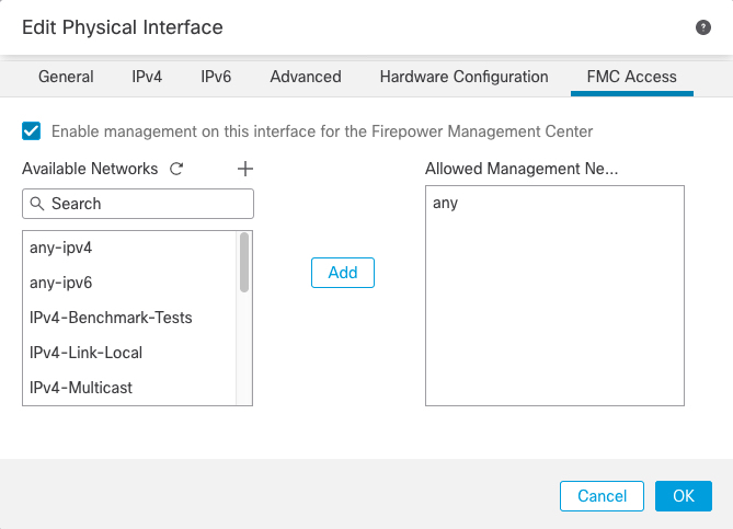
-
Check Enable management on this
interface for the Firepower Management Center to use
this data interface for management instead of the dedicated
Management interface.
-
(Optional) In the Allowed Management Networks
box, add the networks from which you want to allow manager access.
By default, any networks are allowed.
|
Step 16 | Click
OK.
|
Step 17 | Click
Save.
You can now go to and deploy the policy to assigned devices. The changes are not active until you deploy them.
|