Configure an Inline Set

This section enables and names two physical interfaces or EtherChannels that you can add to an inline set. You can also optionally enable Hardware Bypass for supported interface pairs.

Note

For the Firepower 4100/9300, you configure basic interface settings in FXOS on the chassis. See Configure a Physical Interface for more information.

Before you begin

  • If you are using EtherChannels, add them according to Configure an EtherChannel.

  • We recommend that you set STP PortFast for STP-enabled switches that connect to the threat defense inline pair interfaces. This setting is especially useful for Hardware Bypass configurations and can reduce bypass times.

Procedure


Step 1

Select Devices > Device Management and click Edit (edit icon) for your threat defense device. The Interfaces page is selected by default.

Step 2

Click Edit (edit icon) for the interface you want to edit.

Step 3

In the Mode drop-down list, choose None.

After you add this interface to an inline set, this field will show Inline for the mode.

Step 4

Enable the interface by checking the Enabled check box.

Step 5

In the Name field, enter a name up to 48 characters in length.

Do not set the security zone yet; you must set it after you create the inline set later in this procedure.

Step 6

(Optional) Add a description in the Description field.

The description can be up to 200 characters on a single line, without carriage returns.

Step 7

(Optional) Set the duplex and speed by clicking Hardware Configuration.

The exact speed and duplex options depend on your hardware.

  • Duplex—Choose Full, Half, or Auto. Auto is the default.

  • Speed—Choose 10, 100, 1000, or Auto. Auto is the default.

Step 8

Click OK.

Do not set any other settings for this interface.

Step 9

Click Edit (edit icon) for the second interface you want to add to the inline set.

Step 10

Configure the settings as for the first interface.

Step 11

Click Inline Sets.

Step 12

Click Add Inline Set.

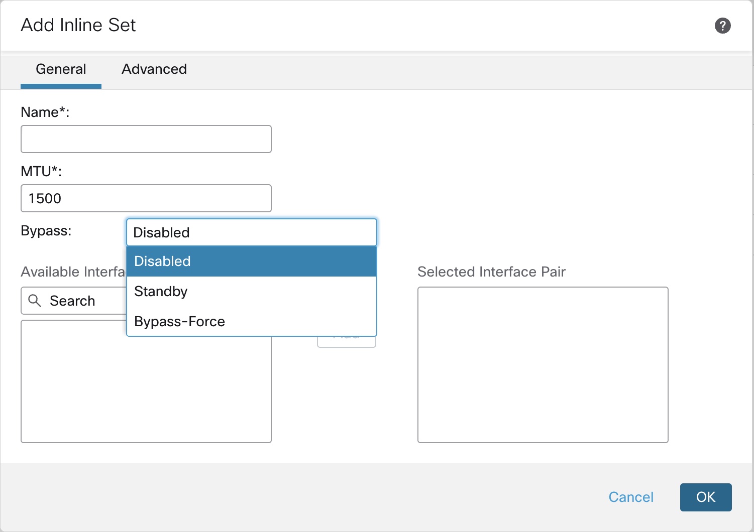
The Add Inline Set dialog box appears with General selected.

Step 13

In the Name field, enter a name for the set.

Step 14

(Optional) Change the MTU to enable jumbo frames.

For inline sets, the MTU setting is not used. However, the jumbo frame setting is relevant to inline sets; jumbo frames enable the inline interfaces to receive packets up to 9000 bytes. To enable jumbo frames, you must set the MTU of any interface on the device above 1500 bytes.

Step 15

Configure Hardware Bypass.

Note

Do not enable Bypass and Propagate Link State for the same inline set.

  1. For the Bypass mode, choose one of the following options:

    • Disabled—Set Hardware Bypass to disabled for interfaces where Hardware Bypass is supported, or use interfaces where Hardware Bypass is not supported.

    • Standby—Set Hardware Bypass to the standby state on supported interfaces. Only pairs of Hardware Bypass interfaces are shown. In the standby state, the interfaces remain in normal operation until there is a trigger event.

    • Bypass-Force—Manually forces the interface pair to go into a bypass state. Inline Sets shows Yes for any interface pairs that are in Bypass-Force mode.

  2. In the Available Interfaces Pairs area, click a pair and then click Add to move it to the Selected Interface Pair area.

    All possible pairings between named and enabled interfaces with the mode set to None show in this area.

Step 16

(Optional) Click Advanced to set the following optional parameters:

  • Tap Mode—Set to inline tap mode.

    Note that you cannot enable this option and strict TCP enforcement on the same inline set.

    Note

    If you need to enable or disable the Tap mode, you should do so during a maintenance window. Changing the mode while the device is passing traffic can cause traffic disruption.

    Note

    Tap mode significantly impacts the threat defense performance, depending on the traffic.

  • Propagate Link State—Configure link state propagation.

    Link state propagation automatically brings down the second interface in the inline interface pair when one of the interfaces in an inline set goes down. When the downed interface comes back up, the second interface automatically comes back up, also. In other words, if the link state of one interface changes, the device senses the change and updates the link state of the other interface to match it. Note that devices require up to 4 seconds to propagate link state changes. Link state propagation is especially useful in resilient network environments where routers are configured to reroute traffic automatically around network devices that are in a failure state.

    Note

    Do not enable Bypass and Propagate Link State for the same inline set.

    Do not enable Propagate Link State when using clustering.

  • Snort Fail Open—Enable or disable either or both of the Busy and Down options if you want new and existing traffic to pass without inspection (enabled) or drop (disabled) when the Snort process is busy or down.

    By default, traffic passes without inspection when the Snort process is down, and drops when it is busy.

    When the Snort process is:

    • Busy—It cannot process traffic fast enough because traffic buffers are full, indicating that there is more traffic than the device can handle, or because of other software resource issues.

    • Down—It is restarting because you deployed a configuration that requires it to restart. See Configurations that Restart the Snort Process When Deployed or Activated.

    When the Snort process is down and comes back up, it inspects new connections. To prevent false positives and false negatives, it does not inspect existing connections on inline, routed, or transparent interfaces because initial session information might have been lost while it was down.

    Note

    When Snort fails open, features that rely on the Snort process do not function. These include application control and deep inspection. The system performs only basic access control using simple, easily determined transport and network layer characteristics.

    Note

    The Strict TCP Enforcement option is not supported.

Step 17

Click Interfaces.

Step 18

Click Edit (edit icon) for one of the member interfaces.

Step 19

From the Security Zone drop-down list, choose a security zone or add a new one by clicking New.

You can only set the zone after you add the interface to the inline set; adding it to an inline set configures the mode to Inline and lets you choose inline-type security zones.

Step 20

Click OK.

Step 21

Set the security zone for the second interface.

Step 22

Click Save.

You can now go to Deploy > Deployment and deploy the policy to assigned devices. The changes are not active until you deploy them.