Configure an EtherChannel

This section describes how to create an EtherChannel port-channel interface, assign interfaces to the EtherChannel, and customize the EtherChannel.

Guidelines

  • You can configure up to 48 EtherChannels, depending on the number of interfaces for your model.

  • Each channel group can have up to 8 active interfaces, except for the ISA 3000, which supports 16 active interfaces. For switches that support only 8 active interfaces, you can assign up to 16 interfaces to a channel group: while only 8 interfaces can be active, the remaining interfaces can act as standby links in case of interface failure.

  • All interfaces in the channel group must be the same media type and speed capacity. The media type can be either RJ-45 or SFP; SFPs of different types (copper and fiber) can be mixed. You cannot mix interface capacities (for example 1GB and 10GB interfaces) by setting the speed to be lower on the larger-capacity interface, except for the Secure Firewall 3100, which supports different interface capacities as long as the speed is set to Detect SFP; in this case the lowest common speed is used.

Note

For the Firepower 4100/9300, you configure EtherChannels in FXOS. See Add an EtherChannel (Port Channel) for more information.

Before you begin

  • You cannot add a physical interface to the channel group if you configured a name for it. You must first remove the name.

    Note

    If you are using a physical interface already in your configuration, removing the name will clear any configuration that refers to the interface.

Procedure


Step 1

Select Devices > Device Management and click Edit (edit icon) for your threat defense device. The Interfaces page is selected by default.

Step 2

Enable the member interfaces according to Enable the Physical Interface and Configure Ethernet Settings.

Step 3

Click Add Interfaces > Ether Channel Interface.

Step 4

On the General tab, set the Ether Channel ID to a number between 1 and 48 (1 and 8 for the Firepower 1010).
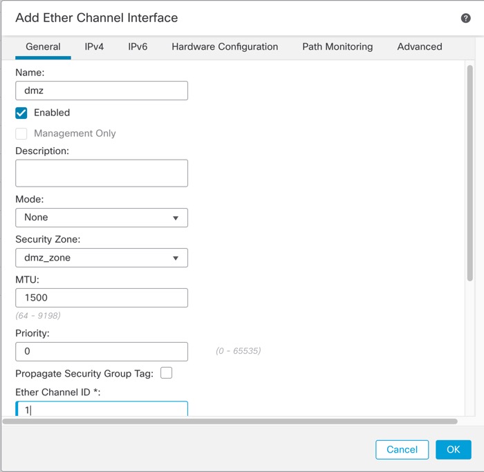
Add EtherChannel Interface

Step 5

In the Available Interfaces area, click an interface and then click Add to move it to the Selected Interfaces area. Repeat for all interfaces that you want to make members.

Make sure all interfaces are the same type and speed capability.
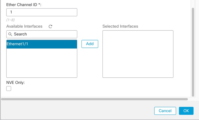
Available Interfaces

Step 6

(Optional) Click the Advanced tab to customize the EtherChannel. Set the following parameters on the Information sub-tab:
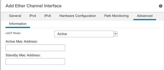
Advanced
Advanced
  • (ISA 3000 only) Load Balancing—Select the criteria used to load balance the packets across the group channel interfaces. By default, the threat defense device balances the packet load on interfaces according to the source and destination IP address of the packet. If you want to change the properties on which the packet is categorized, choose a different set of criteria. For example, if your traffic is biased heavily towards the same source and destination IP addresses, then the traffic assignment to interfaces in the EtherChannel will be unbalanced. Changing to a different algorithm can result in more evenly distributed traffic. For more information about load balancing, see Load Balancing.

  • LACP Mode—Choose Active, Passive, or On. We recommend using Active mode (the default).

  • (ISA 3000 only) Active Physical Interface: Range—From the left drop-down list, choose the minimum number of active interfaces required for the EtherChannel to be active, between 1 and 16. The default is 1. From the right drop-down list, choose the maximum number of active interfaces allowed in the EtherChannel, between 1 and 16. The default is 16. If your switch does not support 16 active interfaces, be sure to set this command to 8 or fewer.

  • Active Mac Address—Set a manual MAC address if desired. The mac_address is in H.H.H format, where H is a 16-bit hexadecimal digit. For example, the MAC address 00-0C-F1-42-4C-DE is entered as 000C.F142.4CDE.

Step 7

Click the Hardware Configuration tab and set the Duplex and Speed for all member interfaces.

Step 8

Click OK.

Step 9

Click Save.

You can now go to Deploy > Deployment and deploy the policy to assigned devices. The changes are not active until you deploy them.

Step 10

(Optional) Add a VLAN subinterface. See Add a Subinterface.

Step 11

Configure the routed or transparent mode interface parameters. See Configure Routed Mode Interfaces or Configure Bridge Group Interfaces.